


Land Surveys
Land Surveys were engaged by an Australian engineering and services company specialising in offshore operations, to provide a 3D As-Built model of a MODU (mobile offshore drilling unit) stationed in Singapore.
Leica MS50 Multi-station
Liscad, Cyclone, Auto Cad
In late 2013 and early 2014, Land Surveys was engaged by an Australian engineering and services company specialising in offshore operations, to provide a 3D ‘As-Built’ model of a MODU (mobile offshore drilling unit) stationed in Singapore.
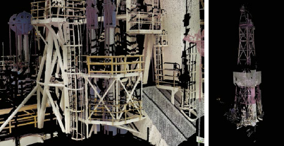
The scope of works was to provide a complete point-cloud dataset and 3D CAD model, to an accuracy of better than +/- 5mm to assist in refurbishment and design of interface equipment fabrication and equipment location planning on the MODU.
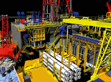
Intricate components and hard-toaccess areas of the MODU, such as the moonpool substructure, drill floor and the derrick needed to be captured in great detail. The end result was a working 3D CAD model of these areas, enabling the client to position equipment, rotate and translate individual elements and provide clash detection, all from within a desktop CAD environment.
Careful planning was required in order to carry out the fieldwork, as the MODU was only scheduled to be docked for refurbishment and maintenance for a period of six days. A project of this scale and level of detail could normally be expected to take in the order of 7-10 days, so execution of fieldwork tasks needed to be perfect to remain on the projects critical path. A three-man survey crew, comprising two HDS scanning units and the Leica MS50 Multi-station, were mobilised from the Land Surveys Perth Headquarters to Singapore, where the MODU was at dock.
On with the job
From there it was straight to work for the surveyors, undertaking a thorough HSE induction and survey reconnaissance of the work area and liaising with MODU staff and the barge master. Extensive fabrication and refurbishment operations were being undertaken at the time of the project, with the deck cranes constantly lifting equipment onto and off the main deck areas. Precision planning and communication with all stakeholders was needed to ensure access to all areas was available for the survey to be completed. It was essential that this was achieved with minimal disruption to the refurbishment operations of the MODU.
Environmental conditions inherent to a floating structure presented unique challenges to the survey team. The constant movement of the floating structure due to waves, wind and tides introduced a range of instrument stability issues where normal survey procedure could not be implemented. Each instrument setup was effectively on its own XYZ coordinate system and the work plane perpendicular to the superstructure, rather the earth’s plumbline. Placement and geometry of dimensional control to enable accurate registration of scan data was therefore critical. A minimum of five points were required to be common between sequential setup and scan areas. It was not only the continuous rolling of the structure with the ocean that caused challenges for our surveyors, they also had to contend with the constant and harmonic vibration
of the huge diesel generators powering the MODU and resonating through the platform and the instruments.
These vibrations made sighting accurately to control targets through the telescope nearly impossible. So by using the Leica MS50 Multi-station’s telescope camera, surveyors were able to pinpoint the control targets through the live imaging display, and the zoom and autofocus made it possible to average out the vibrations and accurately read to the control targets.
Surveyors on the project found the ability to link photographs to specific control points added a layer of useful and essential documentation when processing and adjusting large volumes of control data. The processing team found this functionality particularly helpful during the registration process.
The client’s requirement to capture the 65m-high derrick and drill floor structures posed a number of issues to the team. Due to the continuous operation of MODU, access to certain areas was given to the surveyors in piecemeal fashion and within tight windows of opportunity to complete the required scans. With these limitations in mind, the team needed to be clear, concise and targeted in its approach to each area, and needed to be able to scan different components, at different levels of detail, and verify the completeness of each scan after each setup.
The MS50’s functionality allowed different areas and components of interest to be defined and windowed on the controller screen, and by selecting the appropriate scan mode, the resolution of the data was able to be controlled at different distances from the Multi-station setup. For example, the top of the derrick at a longer distance versus the drill floor deck at a closer distance, were able to be scanned at the appropriate resolution to reduce noise and improve the integrity of the point cloud.
With only one chance to acquire the data, it was a constant race against the clock to complete each scan. Based on known setup routines in the MS50 Multistation (common to conventional total station instrumentation), the point clouds produced in each scan were able to be automatically referenced to the MODU coordinate system. Completed scans were then able to be viewed and verified onscreen for completeness in the field and prior to moving to the next scan station. This functionality and visualisation was vital to be able to capture data critical to the project within tight time frames, and eliminated the risk of costly re-visits.
Over the course of the six-day project, over 150 scans were completed using the HDS units and Multi-station. Registration of the scans delivered a complete homogeneous 3D point cloud, which subsequently allowed low, medium and high-level modelling of componentry as required. In addition, the 3D Tru-View panoramic visualisation provided by the data will continue to be a valuable tool for the MODU operator in managing inspection, maintenance, repair and upgrading of the MODU into the future.
Having a Multi-station at its disposal allowed the team to provide unquestionable efficiency to the workflow, and the ability to establish control and scan critical areas in the same operation.
Under some of the most challenging conditions, by utilising the equipment to its full extent, the team was able to deliver a project of the highest quality within a timeframe that would not have been possible using a conventional total station and scanning equipment.
