

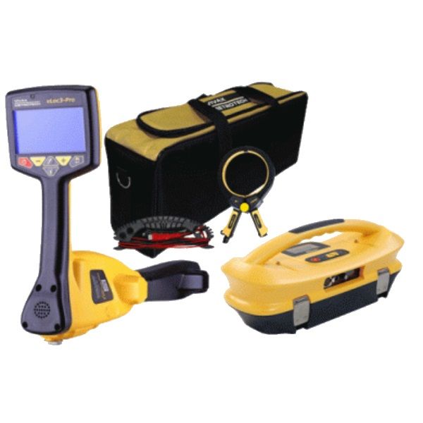
Vivax Metrotech vLoc3-Pro use V3A02T-K02T-COAU
The 10-Watt broadband transmitter has selectable induction and direct connection frequencies from 98Hz to 200kHz, SD mode (Signal Direction), fault find and true resistance measurement up to 1 Mohm. The two inch by one-inch dot matrix display with LED backlight shows output current, connection type, volts, resistance, frequency, volume, battery condition and high voltage warnings.
The optional Transmitter Link (Tx-Link) installed in the receiver and transmitter, remote operation of the transmitter from the receiver is possible. The range of the radio transmitter link depends on having a clear “line of sight” between receiver and transmitter but is typically around 985 ft./300m. Signal Direction (SD) mode feature verifies if the line being located is the target that the transmitter is connected to.
When a transmitter is connected to a target line, the signal travels along it and finds the easiest way to travel back, usually via the ground and ground stake. However, very often the signal will travel back along adjacent utilities which offer an easier route. As a result, there can be multiple signals radiating from utilities in the area making it difficult to identify the target line. These return signals are typically traveling in the opposite direction than the applied signal. The Signal Direction feature identifies which direction the signal is flowing and hence the target line.
Packaged in a lightweight, rugged, ergonomic IP54 housing, the transmitter provides consistent current output in direct connect, clamp or induction modes and protection against incoming voltages up to 240V.
|
Classic Mode Unique in all display modes are the colour codes which give the level of distortion and confidence level. The Classic Screen has all the functions normally seen on a classic cable locator. |
|
|
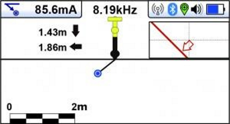
Vector Mode This view is the Vector screen which is a side view, or cross section view. The inset view is the top pan view. Combined the user has a true 3D view. Vector mode allows to measure utilities from a location which is offset. This would potentially allow to detect a utility that is located on a busy road from the safe location of a sidewalk. |
|
|
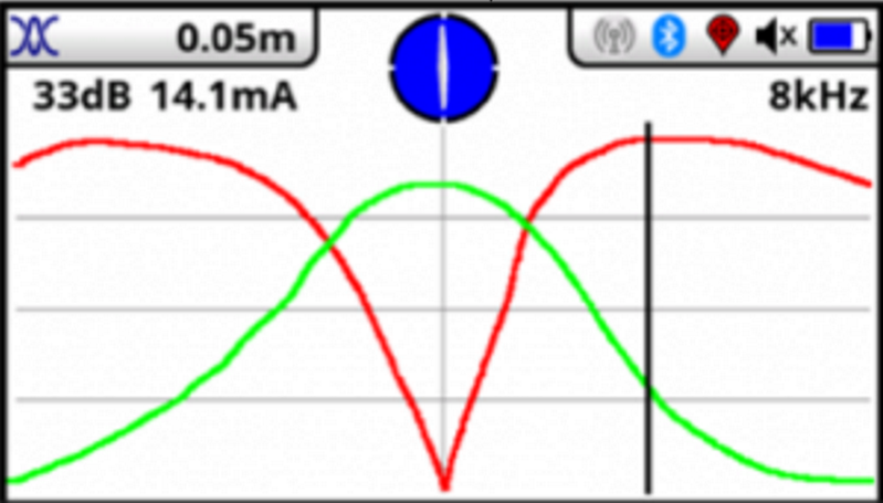
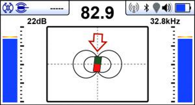
Transverse Mode The Transverse Plot screen is used to analyse the field shape at a particular location. This enables the user to get a better feel for the reliability of the data gathered. Two plots are generated simultaneously
In non-distorted fields, the peak and null positions should coincide, and the shape of the fields should be symmetrical about the centre line. |
|
|
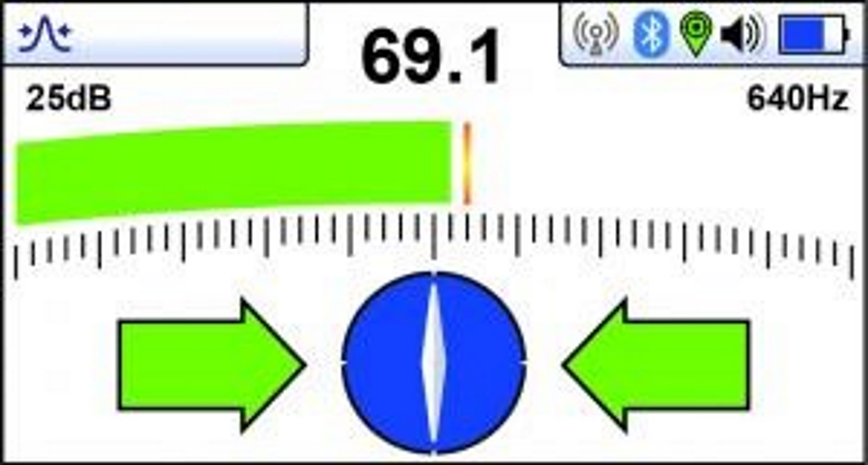
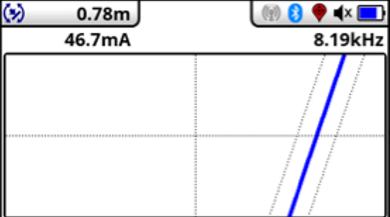
Plan Mode The Plan View screen shows a picture as if you were viewing the line from above the ground. When the blue line in the centre and pointing forward/back you are directly over the line and pointing in the direction of the line. Red, blue and green colour of the line show the level of distortion and confidence level. |
|
|
Sonde Locating Mode The Sonde give a different “Peak” pattern and there are three distinct peaks – a small peak – a large peal - a small peak with two “Nulls” between the peaks. The Sonde is located under the centre of the “large peak” |
|
| Brochures | |
|---|---|
| VLOC3 - Brochure | Product Manuals |
| Vivax Metrotech vLoc3-Pro use V3A02T-K02T-COAU - Product Manual |
Brand: Vivax Metrotech |
Code: V3A02-K02T-CN-AU
APN: V3A02T-K02T-COAU |
|
Classic Mode Unique in all display modes are the colour codes which give the level of distortion and confidence level. The Classic Screen has all the functions normally seen on a classic cable locator. |
|
|
Vector Mode This view is the Vector screen which is a side view, or cross section view. The inset view is the top pan view. Combined the user has a true 3D view. Vector mode allows to measure utilities from a location which is offset. This would potentially allow to detect a utility that is located on a busy road from the safe location of a sidewalk. |
|
|
Transverse Mode The Transverse Plot screen is used to analyse the field shape at a particular location. This enables the user to get a better feel for the reliability of the data gathered. Two plots are generated simultaneously
In non-distorted fields, the peak and null positions should coincide, and the shape of the fields should be symmetrical about the centre line. |
|
|
Plan Mode The Plan View screen shows a picture as if you were viewing the line from above the ground. When the blue line in the centre and pointing forward/back you are directly over the line and pointing in the direction of the line. Red, blue and green colour of the line show the level of distortion and confidence level. |
|
|
Sonde Locating Mode The Sonde give a different “Peak” pattern and there are three distinct peaks – a small peak – a large peal - a small peak with two “Nulls” between the peaks. The Sonde is located under the centre of the “large peak” |
|
